What Causes Current Sensor Drift And How To Reduce It
What Causes Current Sensor Drift And How To Reduce It
Current sensor drift is one of the most common reasons for inaccurate current measurement in power electronics systems. In applications such as battery energy storage systems, EV chargers, solar inverters, motor drives, UPS systems, welding machines, and industrial power supplies, drift can gradually change the sensor output and reduce measurement reliability over time.
This guide explains what causes current sensor drift, how temperature, offset, aging, magnetic interference, power supply variation, and installation conditions affect sensor accuracy, and how engineers can reduce drift through proper sensor selection, calibration, thermal design, shielding, and system testing.
Quick Answer
Current sensor drift is mainly caused by temperature changes, zero offset shift, magnetic core aging, electronic component aging, power supply fluctuation, external magnetic interference, mechanical stress, and poor installation layout. To reduce drift, engineers should choose low-drift current sensors, match the current range correctly, improve thermal design, avoid nearby magnetic interference, use stable power supply, center the conductor, apply calibration, and verify performance under real operating conditions. For high-accuracy applications, closed loop current sensors are usually preferred because they provide better offset stability, linearity, and temperature performance.
1. What Current Sensor Drift Means In Real Applications
Current sensor drift means the sensor output gradually changes even when the actual current remains the same. In many systems, drift appears as zero offset drift, gain drift, temperature drift, or long-term output deviation. At first, the error may be small, but in precision control and safety monitoring applications, even a small drift can affect system decisions.
For example, in a battery energy storage system, current sensor drift may affect charge and discharge current calculation, SOC estimation, energy statistics, and protection logic. In a motor drive, drift may affect torque feedback and current control. In an EV charger, drift may affect charging current regulation and safety monitoring. In solar inverters and UPS systems, drift may reduce long-term measurement stability and fault detection accuracy.
Drift is not always caused by poor product quality. It may come from normal temperature changes, long operating hours, high-power cabinet heat, unstable power supply, strong electromagnetic interference, incorrect conductor position, or insufficient calibration. That is why current sensor drift should be considered during both product selection and system design.
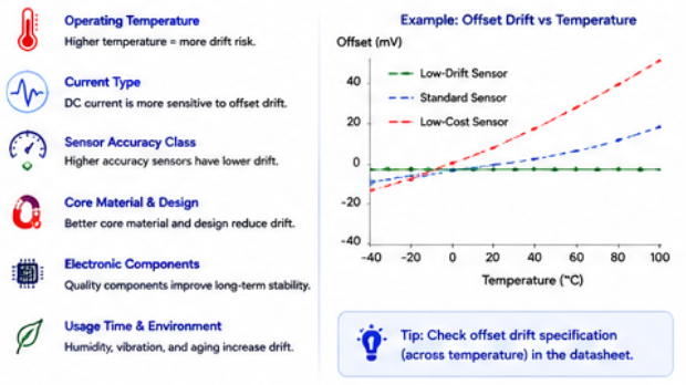
When comparing current sensor models, buyers should not only check accuracy at room temperature. They should also review offset drift, temperature coefficient, long-term stability, operating temperature range, response behavior, and test data under real working conditions. A sensor that performs well in a laboratory may still drift in a high-temperature, high-current, high-EMI industrial environment.
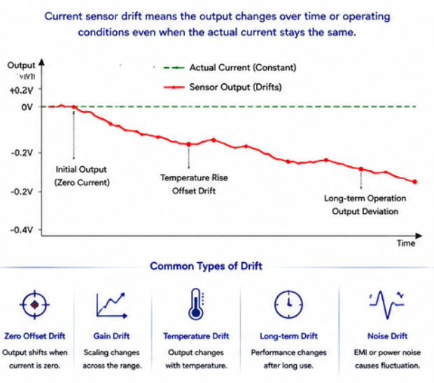
Common Types Of Current Sensor Drift
Zero offset drift: the sensor output shifts when the actual current is zero.
Gain drift: the output scaling changes across the measurement range.
Temperature drift: output changes as ambient or internal temperature changes.
Long-term drift: output changes after long operating hours or aging.
Magnetic drift: magnetic core or nearby magnetic fields affect sensor output.
Power supply related drift: unstable supply voltage changes sensor output stability.
2. Main Causes Of Current Sensor Drift
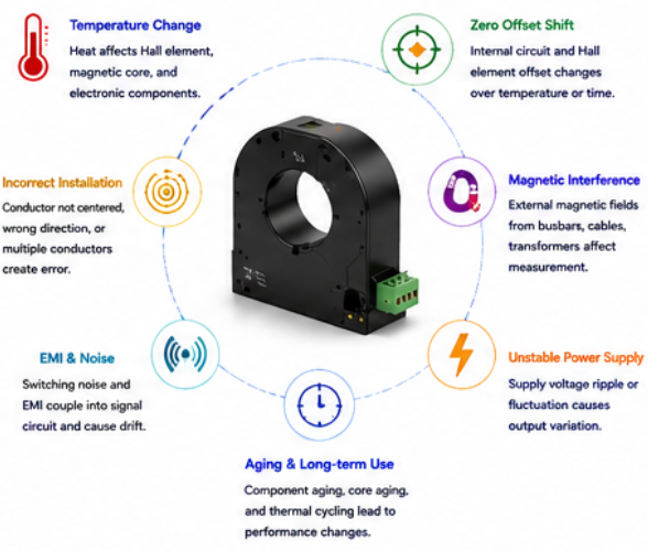
Temperature is one of the biggest causes of current sensor drift. Power electronics equipment often generates heat during operation. Motor drive cabinets, EV charging modules, battery energy storage cabinets, inverters, and welding machines may operate under high temperature. As temperature changes, the magnetic core, Hall element, compensation circuit, amplifier, and other internal components may change their characteristics, causing output drift.
Zero offset drift is another common issue. When the actual current is zero, the sensor should output a defined zero-current signal. If this output shifts over temperature or time, the measurement system may report a false current. This is especially important in DC current measurement, battery systems, leakage monitoring, and low-current accuracy applications.
Magnetic interference can also cause drift or unstable readings. Nearby high-current cables, busbars, transformers, inductors, motor phases, and power modules may create magnetic fields that influence the sensor. If the conductor is not centered in the sensor aperture or the sensor is installed too close to other high-current paths, measurement error may increase.
Power supply quality matters as well. Some current sensors require a stable supply voltage to maintain accurate output. If the supply is noisy, unstable, or affected by switching power circuits, the sensor output may fluctuate or drift. Proper filtering, grounding, shielding, and power design can help reduce this problem.
Long-term aging and mechanical stress may also affect drift. Vibration, thermal cycling, humidity, dust, and repeated load changes can gradually affect sensor performance. For high-reliability industrial equipment, buyers should request reliability data, temperature test data, aging tests, insulation tests, and batch quality control documents when necessary.
| Drift Cause | How It Affects Measurement | How To Reduce It |
|---|---|---|
| Temperature Change | Changes offset, gain, and electronic component behavior | Choose low-temperature-drift sensors and improve thermal design |
| Zero Offset Drift | Creates false current reading at zero current | Use zero calibration and low-offset sensor technology |
| Magnetic Interference | Nearby busbars or cables disturb the magnetic field | Increase spacing, optimize conductor layout, and use shielding if needed |
| Incorrect Conductor Position | Off-center conductor position creates uneven magnetic field detection | Keep the cable or busbar centered in the sensor aperture |
| Unstable Power Supply | Power noise or voltage fluctuation affects sensor output | Use stable isolated supply, filtering, and proper grounding |
| Aging And Thermal Cycling | Long-term operation may change output stability | Request reliability test data and verify long-term performance |
| EMI And Signal Noise | Switching circuits create unstable or noisy output | Use shielded signal cables, proper routing, filtering, and grounding |
| Wrong Sensor Technology | Sensor structure may not meet accuracy or stability needs | Use closed loop or precision sensors for demanding applications |
Why Closed Loop Sensors Usually Reduce Drift Better
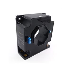
Closed loop current sensors use compensation feedback to improve measurement stability. Compared with many open loop designs, closed loop sensors usually provide better linearity, lower offset, faster response, and better temperature performance. For applications where drift directly affects BMS calculation, motor torque control, EV charging accuracy, or inverter protection, closed loop current sensors are often a better choice.
3. How To Reduce Current Sensor Drift In System Design
The first step is to choose a sensor with suitable accuracy and drift performance. Buyers should review datasheet values for accuracy, offset, temperature drift, linearity, response time, and operating temperature range. For high-accuracy applications, ask the supplier for test data under different temperatures and current levels, not only a single accuracy value at room temperature.
Thermal design is very important. Avoid placing current sensors too close to heat sources such as IGBT modules, SiC MOSFETs, DC-link capacitors, busbars, transformers, and power resistors. Improve airflow, heat dissipation, and cabinet layout. If the sensor must work in a hot environment, select a model with low drift and wide operating temperature range.
Installation layout should reduce magnetic interference. Keep the primary conductor centered inside the sensor aperture. Avoid placing sensors close to other high-current cables or busbars. If several conductors are nearby, review current direction and magnetic field interaction. For high-current or compact systems, the physical layout can be just as important as the sensor specification.
Signal wiring should be designed carefully. Use shielded or twisted-pair cables when needed, separate signal wires from power cables, and avoid long unshielded runs in noisy environments. Stable power supply, proper grounding, and filtering can reduce noise-related drift and improve output stability.
Finally, calibration and verification should be done under real operating conditions. Factory calibration is useful, but actual system conditions may include temperature rise, switching noise, vibration, and load changes. For precision systems, zero calibration, multi-point calibration, temperature compensation, and final system testing can help reduce drift-related measurement error.
Application Matching Reference
| Application | Main Drift Risk | Recommended Reduction Method |
|---|---|---|
| Battery Energy Storage System | DC offset drift affects charge/discharge current data | Use low-offset bidirectional current sensor and verify under temperature |
| EV Charger | High-power heat and switching noise affect measurement stability | Use stable isolated sensor, shielding, and proper thermal layout |
| Solar Inverter | Outdoor temperature variation and inverter switching noise | Choose low-temperature-drift sensor and improve EMC design |
| Motor Drive / Servo Drive | Drift affects torque feedback and current loop control | Use closed loop current sensor with fast response and low drift |
| UPS System | Long-term operation causes offset and temperature-related deviation | Use stable DC current sensor and perform periodic verification |
| Welding Machine | High pulse current and heat create output instability | Check peak current capability, thermal rating, and overload tolerance |
Common Mistakes To Avoid
Checking only room-temperature accuracy and ignoring temperature drift.
Using a low-cost open loop sensor for high-precision DC feedback.
Installing the sensor near strong heat sources or magnetic fields.
Allowing the conductor to pass off-center through the sensor aperture.
Using long unshielded signal cables in noisy power electronics systems.
Ignoring zero offset calibration in battery and DC current applications.
Not testing sensor drift under real current, temperature, and load conditions.
Conclusion
Current sensor drift is mainly caused by temperature changes, zero offset shift, magnetic interference, power supply instability, aging, EMI noise, and improper installation. In high-value power electronics systems, drift can affect control accuracy, safety protection, energy calculation, and long-term equipment reliability.
To reduce drift, engineers should choose the correct sensor technology, review temperature drift data, improve thermal layout, avoid external magnetic interference, stabilize the power supply, use proper wiring and grounding, and calibrate the system under real operating conditions. For demanding applications such as BESS, EV chargers, solar inverters, motor drives, and UPS systems, low-drift closed loop current sensors are often the safer selection direction.
FAQ
1. What is current sensor drift?
Current sensor drift means the sensor output changes over temperature, time, or operating conditions even when the actual current does not change. It may appear as offset drift, gain drift, or long-term output deviation.
2. What causes current sensor drift?
Common causes include temperature changes, zero offset shift, magnetic interference, unstable power supply, aging, EMI noise, conductor misalignment, and poor installation layout.
3. Why is drift important in battery energy storage systems?
In battery energy storage systems, current sensor drift can affect charge and discharge current data, SOC estimation, energy calculation, battery protection, and system diagnostics.
4. Are closed loop current sensors better for reducing drift?
Yes, in many demanding applications. Closed loop current sensors usually provide better offset stability, linearity, response time, and temperature performance than many open loop current sensors.
5. What information should I provide before requesting a low-drift current sensor quote?
You should provide the application, current type, rated current, peak current, accuracy target, offset drift requirement, temperature range, output signal, isolation requirement, conductor size, and installation environment.
Contact Us For Low-Drift Current Sensor Selection Support
If you are selecting low-drift current sensors for battery energy storage systems, EV chargers, solar inverters, motor drives, UPS systems, welding machines, or industrial power electronics, send us your current range, accuracy target, offset drift requirement, temperature range, output signal, and application details. Our team can help you match a suitable current sensor solution.
Contact Us Get Quote