Open Loop vs Closed Loop Current Sensors: Accuracy, Cost and Application Fit
Open Loop vs Closed Loop Current Sensors: Accuracy, Cost and Where Each Belongs
Every inverter, servo drive, UPS and EV charger measures current — and the choice between open loop and closed loop Hall-effect sensors shapes the accuracy, bandwidth and cost of that measurement. Both use the same physical core idea; they differ in how they treat the magnetic circuit. Here is the engineering trade-off, without the marketing gloss.
1. How each principle works
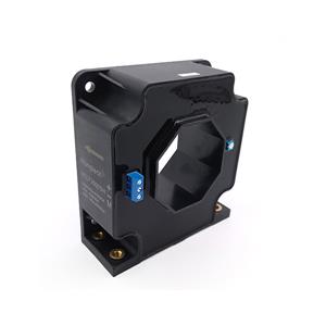
An open loop sensor passes the primary conductor through a magnetic core with a Hall element in the gap; the Hall voltage is amplified directly into the output. A closed loop sensor adds a compensation winding driven to cancel the core flux to zero; the compensation current — an exact scaled copy of the primary — becomes the output. The closed loop keeps the core at zero flux, which is where all its advantages come from.
2. What zero-flux buys you
Linearity and gain error improve roughly an order of magnitude (closed loop typically 0.2-0.5% vs 1-2% open loop); temperature drift shrinks because core nonlinearity and Hall drift are compensated; bandwidth extends (100-200kHz class vs 20-50kHz); and response time drops below 1µs — vital for short-circuit protection of fast power stages. The price: the compensation winding needs supply current proportional to the measured current, the sensor is larger, and it costs more.
3. Where open loop is the right answer
Battery monitoring, DC panels, general inverter phase current where 1-2% is ample, cost-sensitive high-volume products, and high-current busbars where compensation power would be prohibitive. Modern open loop designs with programmable Hall ICs have narrowed the accuracy gap — for many industrial drives they are now the default, and their low power draw suits battery systems.
4. Where closed loop earns its cost
Servo drives needing smooth low-speed torque (offset and noise show up as torque ripple), precision test equipment, medical power supplies, and any protection path where µs-class response prevents IGBT/SiC failure. For the highest accuracy classes (0.01-0.1%), flux-gate technology extends the closed-loop principle further — energy metering, battery test systems and calibration equipment live there.
5. Specification checklist
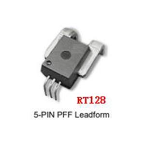
Define: nominal and peak current, required accuracy over temperature (not just at 25°C), bandwidth and response time, supply voltage available (±15V traditional, 5V single-supply modern), output type (voltage, current, ratiometric), isolation voltage and creepage per your safety standard, and aperture or busbar geometry. Rongtech stocks open loop, closed loop and flux-gate sensors alongside the power semiconductors they protect (IGBT, SiC/GaN, IPM) — send your application parameters and we will return matched sensor options with datasheets and samples, typically within one working day.