Current Sensor Replacement Guide Output Signal Pin Definition And Aperture Matching
Current Sensor Replacement Guide Output Signal Pin Definition And Aperture Matching
Current sensor replacement is common in EV chargers, BESS cabinets, PCS systems, solar inverters, UPS equipment, welding machines, motor drives, railway power systems and industrial power electronics. Buyers may need a replacement sensor because the original model is expensive, difficult to source, discontinued, too slow to deliver, or not flexible enough for OEM customization.
However, replacing a current sensor is not only about choosing the same current rating. Output signal, pin definition, aperture size, mounting dimensions, supply voltage, isolation voltage, zero-current output, current direction, response time and mechanical installation must all be checked before approving a replacement model.
Quick Answer
To replace a current sensor correctly, buyers should confirm three key areas first: output signal matching, pin definition matching and aperture matching. The replacement sensor must provide a signal that the controller can read, use a wiring or pin layout that can be connected safely, and physically fit the busbar or cable inside the equipment. Buyers should provide the original model number, datasheet, wiring diagram, product photos, output signal, supply voltage, pin definition, aperture size, busbar or cable dimensions, mounting hole distance, isolation requirement and application details before requesting a replacement quote.
1. Why Current Sensor Replacement Often Fails
Many buyers search for a replacement current sensor by only comparing rated current. For example, they may ask for a replacement 500A current sensor, 1000A current sensor or 2000A current sensor. But in real power electronics systems, the same rated current does not mean the same electrical behavior or mechanical fit.
A replacement sensor may have the same current range but a different output signal. A 0-5V output sensor cannot directly replace a 4-20mA model unless the controller supports both. A sensor with 2.5V zero-current output cannot replace a unidirectional 0-5V model without checking the controller logic. A sensor with the correct output may still fail if the pin definition or connector direction is different.
Mechanical fit is another common problem. A replacement current sensor may have the correct electrical specification, but the aperture may be too small for the copper busbar or DC cable. The mounting holes may not match the original cabinet layout. The connector may face the wrong direction. These details can create redesign costs and delay sample approval.

Common Replacement Scenarios
Replacing imported current sensors with China alternative models.
Finding a second-source current sensor for OEM production.
Replacing discontinued current sensor models in existing equipment.
Reducing current sensor cost for EV charger and BESS mass production.
Changing aperture size to fit new busbar or cable layouts.
Customizing output signal or pin definition for existing controllers.
2. Confirm Output Signal Before Comparing Price
Output signal is the first parameter to check when replacing a current sensor. The output signal must match the controller, ADC input, PLC, BMS, PCS controller, inverter control board, EV charger controller or monitoring system. If the replacement sensor output does not match the controller input, the equipment may display wrong current, calculate wrong current direction or trigger false alarms.
Common current sensor output signals include 0-5V, 0-10V, ±5V, ±10V, 4-20mA, CAN, RS485, relay output, switch output and customized output. For compact control boards, 0-5V output is often used. For industrial PLC systems, 0-10V or 4-20mA may be required. For smart power systems, CAN or RS485 may be selected.
For bidirectional DC current measurement, buyers must check zero-current output. Some sensors use midpoint output, such as 2.5V at zero current in a 0-5V system. Some use bipolar output, such as ±5V. If the replacement sensor uses a different zero point, the controller may read charging current as discharging current, or calculate the wrong current value.

| Output Signal | Replacement Risk | Buyer Should Confirm |
|---|---|---|
| 0-5V | Controller may require a specific zero point and scaling | Input range, zero-current output, full-scale current and signal ground |
| 0-10V | May damage or overload a 0-5V controller input | Controller voltage input range and maximum input voltage |
| ±5V / ±10V | Bipolar signal may not match unipolar controller input | Bipolar input support and current direction logic |
| 4-20mA | Voltage input controller cannot read current-loop signal directly | Loop power, load resistance, wiring method and output scaling |
| CAN / RS485 | Protocol mismatch may stop communication | Protocol, address, baud rate, data format and communication distance |
| Custom Output | Supplier cannot customize without original signal details | Original output range, scaling, zero point, polarity and connector |
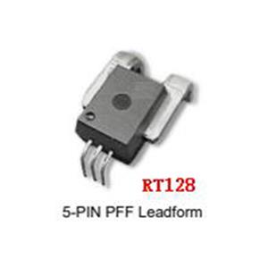
3. Check Pin Definition And Wiring Before Installation
Pin definition is another critical replacement factor. Even if the output signal is the same, the wiring order may be different. A replacement current sensor may use different pins for power supply, ground, output signal, reference voltage, shield, communication lines or alarm output. If the wiring is connected incorrectly, the sensor may output wrong data or become damaged.
Buyers should compare the original sensor wiring diagram with the replacement sensor wiring diagram before installation. For connector-type sensors, the connector model, pin number, terminal direction and cable exit direction should also be checked. For wire-lead sensors, wire color definition and cable length should be confirmed.
In EV charger, BESS, PCS and inverter projects, a wrong pin connection may affect current feedback, protection logic, communication data or controller safety. Therefore, pin definition should be checked before sample testing, not after cabinet assembly.

| Pin / Wiring Item | Why It Matters | Buyer Should Confirm |
|---|---|---|
| Power Supply Pin | Wrong supply connection may damage the sensor | +5V, +12V, +15V, +24V, ±15V or project-specific supply |
| Ground Pin | Ground mismatch may cause unstable output | Signal ground, power ground and shield grounding method |
| Output Pin | Wrong output wiring causes wrong controller reading | Voltage output, current output, digital output or alarm output |
| Reference Pin | Some sensors require reference voltage or midpoint signal | Vref, zero-current reference or custom reference definition |
| Connector Type | Affects direct replacement and assembly process | Connector model, pin count, terminal direction and cable exit direction |
| Cable Definition | Wire color mismatch may cause connection errors | Wire color, cable length, shield, plug and label requirement |
4. Match Aperture Size With Busbar Or Cable
Aperture matching determines whether the replacement current sensor can actually be installed. Many power electronics systems use copper busbars, laminated busbars, thick DC cables, multi-core cables or parallel conductors. A replacement sensor must have enough aperture space for the real conductor, including insulation layer and installation tolerance.
For busbar installation, buyers should provide busbar width, busbar thickness, insulation layer, installation direction and available space. For cable installation, buyers should provide full cable outer diameter, not only conductor cross-section. If the cable cannot be disconnected, a split core current sensor may be considered.
Aperture shape also matters. A round aperture may be suitable for cables, but not ideal for wide flat busbars. A rectangular window may be better for busbar installation. For OEM equipment, a custom aperture can reduce installation difficulty and improve cabinet layout compatibility.
| Aperture Matching Item | Replacement Risk | Buyer Should Provide |
|---|---|---|
| Busbar Width | Busbar may not pass through the window | Width of copper busbar, including coating or insulation if any |
| Busbar Thickness | Insufficient clearance may create installation stress | Thickness and insulation layer thickness |
| Cable Outer Diameter | Cable may not fit even if conductor size seems correct | Full cable diameter including insulation |
| Aperture Shape | Round hole may not suit a flat busbar layout | Round aperture, rectangular aperture, split core or custom window |
| Installation Direction | Sensor body or terminal may interfere with nearby components | Horizontal busbar, vertical busbar, top entry, bottom entry or side entry |
| Available Space | Body size may not fit the cabinet | Available height, width, depth and nearby component layout |
5. Do Not Ignore Isolation Voltage And Safety Requirements
In high-power equipment, current sensors often measure current on a high-current or high-voltage conductor while sending a low-voltage signal to the controller. The replacement sensor must provide proper isolation between the primary conductor side and the secondary signal side.
Buyers should check working voltage, isolation voltage, creepage distance, clearance distance, insulation material and operating environment. This is especially important for EV chargers, battery energy storage systems, PCS cabinets, solar inverters, UPS systems and railway power equipment.
A low-cost replacement model may look suitable by current range, but if the isolation voltage is insufficient, it can create safety risk or fail project testing. Replacement should not reduce the safety margin of the original system.
| Safety Item | Why It Matters | Buyer Should Confirm |
|---|---|---|
| Working Voltage | Defines long-term insulation requirement | System voltage, DC bus voltage or conductor voltage level |
| Isolation Voltage | Protects controller and low-voltage signal circuit | 2.5kV, 4kV, 6kV, 10kV or project-specific requirement |
| Creepage And Clearance | Important for high-voltage insulation safety | Voltage level, pollution degree, altitude and cabinet layout |
| Operating Environment | Heat, dust, humidity and vibration affect reliability | Cabinet temperature, protection level and installation condition |
6. What Buyers Should Send Before Requesting A Replacement Quote
To receive a reliable replacement recommendation, buyers should provide complete original sensor information and application details. A photo alone is usually not enough. The supplier needs the original model number, datasheet, wiring definition, output signal, supply voltage, current range, aperture size, mounting dimensions, isolation requirement and equipment application.
If the original model cannot be identified, buyers should provide clear photos of the sensor label, product body, connector, aperture, mounting holes and installation position. Cabinet photos and busbar or cable dimensions are also very useful for checking mechanical compatibility.
Example Replacement Request:
Application: BESS cabinet bidirectional DC current measurement
Original sensor: Model number and datasheet provided
Current range: 1000A rated, 1500A peak
Output signal: 0-5V with 2.5V zero-current output
Supply voltage: +15V
Pin definition: Vcc, GND, Vout, shield, connector type provided
Aperture requirement: Copper busbar 60 × 8 mm with insulation
Isolation requirement: 4kV or higher
Required support: Direct replacement or customized alternative
Quantity: 10 samples first, estimated annual demand 3000 pieces
Final Replacement Checklist
Provide original current sensor model number and datasheet.
Send product photos, label photos, connector photos and installation photos.
Confirm rated current, peak current and current type.
Match output signal, output scaling and zero-current output.
Confirm supply voltage, pin definition and wiring sequence.
Check connector type, wire color, cable length and cable exit direction.
Confirm aperture size, busbar dimensions or cable outer diameter.
Compare mounting holes, body size and available installation space.
Check isolation voltage, working voltage, creepage and clearance.
Test samples in real equipment before mass production approval.
Conclusion
Current sensor replacement should not be based only on current rating or product appearance. Output signal, pin definition and aperture matching are the three most important checks before approving a replacement model. Buyers should also confirm supply voltage, zero-current output, isolation voltage, mounting dimensions, response time, accuracy and real operating conditions.
For EV chargers, BESS cabinets, PCS systems, inverters, UPS equipment and industrial power electronics, a complete replacement parameter list helps the supplier recommend a direct replacement, similar model or customized current sensor solution more accurately.
FAQ
1. What is the most important factor when replacing a current sensor?
Output signal matching is usually the most important factor. The replacement sensor must provide a signal that the controller can read correctly, including output range, scaling, zero-current point and polarity.
2. Can a 0-5V current sensor replace a 4-20mA current sensor?
Not directly, unless the controller supports both signal types or an additional signal conversion circuit is used. The output signal must match the controller input.
3. Why is pin definition important for replacement?
Different sensors may use different wiring orders for power supply, ground, output, reference signal, shield or communication lines. Wrong wiring may cause unstable output, wrong current reading or sensor damage.
4. What should I check for aperture matching?
Buyers should check busbar width, busbar thickness, insulation layer, cable outer diameter, aperture shape, installation direction and available cabinet space.
5. What should I provide before requesting a replacement quote?
Provide the original model number, datasheet, output signal, pin definition, supply voltage, aperture size, mounting dimensions, installation photos, current range, isolation requirement, sample quantity and annual demand.
Request A Current Sensor Replacement Evaluation
If you need to replace a current sensor in EV chargers, BESS cabinets, PCS systems, inverters, UPS equipment or industrial power electronics, send us the original model number, datasheet, output signal, pin definition, aperture size, installation photos, sample quantity and annual demand. Our team can help you evaluate a direct replacement, similar model or customized current sensor solution.
Contact Us Get QuoteRelated Rongtech Sensor Pages
For current sensor selection and OEM project matching, buyers often compare rated current or voltage, aperture size, output signal, insulation level, response time, drift, installation space and project documentation in the same RFQ. The following Rongtech pages connect this article with related sensor categories and quotation paths on the same website.
- Products
- Open Loop Current Sensor
- Close Loop Current Sensor
- Voltage Sensors
- Flux Gate Current Voltage Sensors
- Sensor ICs
- Leakage Current Sensors
- High Precision Shunt Resistor
- High Voltage Current Voltage Transformers
- Contact Rongtech
Inquiry Information To Prepare
A clear inquiry should include rated current or voltage, power supply, output signal, aperture or package size, accuracy class, insulation requirement, working temperature, connector preference, expected quantity and the target equipment type. This makes the article more useful for technical buyers and gives the sales team a stronger route from reading to inquiry.