Current Sensor Installation Guide: Common Mistakes To Avoid
Current Sensor Installation Guide: Common Mistakes To Avoid
Correct current sensor installation is just as important as choosing the right sensor model. Even a high-accuracy current sensor can produce unstable or inaccurate readings if the conductor is off-center, the wiring direction is wrong, the output signal is mismatched, or the sensor is installed too close to high-current busbars, transformers, heat sources, or strong electromagnetic interference.
This guide explains the most common current sensor installation mistakes and how to avoid them in motor drives, EV chargers, solar inverters, UPS systems, battery energy storage systems, welding machines, railway power systems, and industrial control cabinets.
Quick Answer
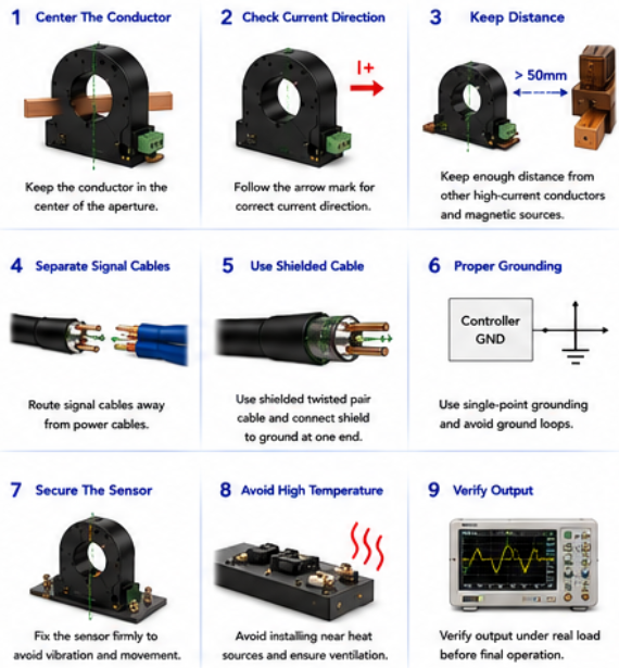
To install a current sensor correctly, keep the conductor centered in the sensor aperture, follow the current direction mark, match the output signal with the controller, avoid nearby high-current conductors and magnetic fields, use proper shielding and grounding, keep signal cables away from power cables, secure the sensor mechanically, control temperature, and verify sensor output under real operating conditions. Most installation errors come from conductor position, wiring direction, signal mismatch, poor grounding, excessive heat, and ignoring electromagnetic interference.
1. Why Installation Quality Affects Current Sensor Accuracy
Many current sensor problems are not caused by the sensor itself. In real industrial applications, inaccurate current readings often come from poor installation. A current sensor measures the magnetic field or electrical signal generated by current flow. If the conductor position, direction, wiring, grounding, or surrounding environment is wrong, the output signal may shift, fluctuate, or become noisy.
For through-hole and Hall effect current sensors, conductor position is especially important. The conductor should usually pass through the center of the sensor aperture. If the cable or busbar is too close to one side, the magnetic field distribution may become uneven and cause measurement error. This is more noticeable in high-current applications and precision feedback systems.
Current direction also matters. Many current sensors have a direction mark, arrow, or polarity indicator. If the conductor passes through the sensor in the wrong direction, the output polarity may be reversed. For bidirectional current measurement, battery charge/discharge monitoring, inverter feedback, or motor control, reversed polarity can cause serious control or diagnostic problems.
Electrical noise is another common issue. Current sensors are often installed near IGBT modules, SiC MOSFETs, contactors, busbars, transformers, motors, DC-link capacitors, and switching power supplies. These components may generate strong electromagnetic interference. Without proper wiring, shielding, and grounding, the current sensor output may become unstable even when the sensor model is correct.
Common Installation Risks
Conductor not centered inside the sensor aperture.
Current direction reversed during installation.
Sensor installed too close to other high-current cables or busbars.
Signal cables routed together with power cables.
Poor grounding or ground loop problems.
Wrong output signal connected to the controller or PLC.
Sensor mounted near heat sources or strong vibration.
2. Common Current Sensor Installation Mistakes And How To Avoid Them
The most common mistake is selecting the correct sensor but installing the conductor incorrectly. For many through-hole current sensors, the conductor should be placed in the center of the aperture. If the conductor touches the inner wall or is positioned unevenly, measurement accuracy may be affected. For busbar installation, engineers should also check busbar size, orientation, and distance from the sensor body.
Another common mistake is ignoring current direction. If the output polarity is reversed, the controller may interpret charging current as discharging current, or positive motor current as negative current. This can affect BMS calculation, inverter control, motor drive feedback, or safety protection. Always confirm the sensor arrow, current direction, and output polarity before final wiring.
Output signal mismatch is also a frequent problem. Some current sensors output voltage signals, some output current signals, and some provide digital or customized outputs. The sensor output must match the controller, ADC, PLC, meter, or monitoring system. Connecting the wrong output type may cause incorrect readings, signal saturation, or even damage to the input circuit.
Poor signal cable routing can create noise problems. Signal cables should not be bundled with high-current power cables, motor cables, switching power lines, or contactor wiring. In noisy environments, shielded cable, twisted-pair wiring, proper grounding, and filtering may be needed. For long-distance transmission, current output or digital communication may be more stable than low-level voltage output.
Mechanical installation should not be ignored. The sensor should be fixed securely to avoid movement, vibration, or stress on terminals. Loose mounting may cause unstable readings, connector fatigue, or long-term reliability issues. In high-current and high-temperature cabinets, thermal expansion and vibration should be considered during layout design.
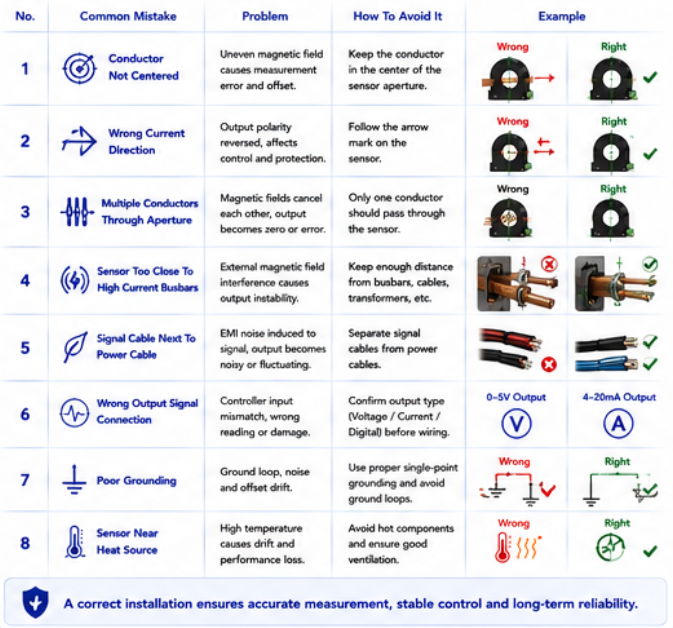
| Installation Mistake | Possible Problem | Correct Practice |
|---|---|---|
| Conductor Off-Center | Uneven magnetic field and increased measurement error | Keep the conductor centered inside the sensor aperture |
| Wrong Current Direction | Output polarity reversed and control logic error | Follow the sensor arrow or current direction mark |
| Near High-Current Conductors | External magnetic field interference | Increase distance from busbars, transformers, and power cables |
| Wrong Output Connection | Incorrect signal reading or controller input mismatch | Match voltage, current, or digital output with controller input |
| Poor Grounding | Noise, offset error, signal fluctuation, or ground loop | Use proper grounding strategy and avoid unnecessary ground loops |
| Signal Cable Near Power Cable | EMI noise coupled into sensor output | Separate signal cables from power cables and use shielding if needed |
| Weak Mechanical Mounting | Vibration, connector stress, unstable readings | Secure the sensor with proper screws, brackets, or mounting structure |
| Installing Near Heat Sources | Temperature drift and reduced long-term stability | Keep away from hot components and improve airflow |
Why Installation Testing Is Necessary
After installation, engineers should verify the sensor output under real operating conditions. A simple no-load test is not enough for high-power systems. The sensor should be checked at different current levels, temperatures, load conditions, switching states, and fault protection scenarios. This helps confirm that installation quality meets the actual system requirement.
3. Installation Tips For Different Applications
In motor drives and VFDs, current sensors are often installed near inverter output phases or DC bus circuits. These areas can have strong switching noise and high dv/dt. Signal cables should be routed away from motor cables and power modules. For servo drives and precision motor control, sensor alignment, response time, and output stability are especially important.
In EV chargers and battery energy storage systems, current sensors may monitor battery current, DC bus current, charging current, or leakage current. Bidirectional current direction should be confirmed carefully. For high-voltage systems, isolation voltage, creepage distance, clearance distance, and safe wiring layout should be reviewed before installation.
In solar inverters and UPS systems, current sensors may operate continuously for long hours. Temperature drift, ventilation, signal stability, and EMC performance matter. Avoid installing sensors too close to DC-link capacitors, power modules, inductors, transformers, or heat sinks unless the layout has been verified.
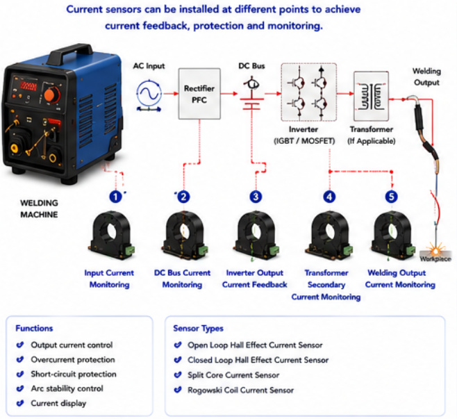
In welding machines, current sensors may face high pulse current, high temperature, vibration, and strong electrical noise. The sensor should be mounted securely and protected from mechanical stress. Peak current, duty cycle, wiring direction, and overload conditions should be tested under real welding operation.
For retrofit projects, split core current sensors are often used because they can be installed without disconnecting existing cables. However, the aperture size, locking structure, cable position, output signal, and installation direction still need careful checking. Easy installation does not mean installation quality can be ignored.
Application Installation Reference
| Application | Installation Focus | Common Mistake To Avoid |
|---|---|---|
| Motor Drives / VFDs | Avoid switching noise and ensure fast feedback stability | Routing signal cables beside motor output cables |
| EV Charging Stations | High-voltage isolation and stable DC current measurement | Ignoring bidirectional current polarity and isolation requirements |
| Battery Energy Storage Systems | Battery charge/discharge current direction and low drift | Installing the sensor in the wrong current direction |
| Solar Inverters | Temperature stability and EMC performance | Installing near hot power modules without thermal margin |
| Welding Machines | High pulse current, vibration, and strong interference | Weak mechanical fixing and no real welding load test |
| Retrofit Power Monitoring | Aperture size, split core locking, and easy installation | Choosing an aperture that does not fit the existing cable or busbar |
Final Installation Checklist
Confirm current type, rated current, peak current, and overload conditions.
Check sensor direction mark and output polarity before wiring.
Keep the conductor centered inside the sensor aperture.
Confirm aperture size, busbar size, and installation space.
Separate signal cables from high-power cables and switching circuits.
Use shielding, grounding, and filtering when the environment is noisy.
Secure the sensor mechanically to reduce vibration and movement.
Verify output signal with the real controller, PLC, ADC, or monitoring system.
Test current measurement at real load, peak current, and operating temperature.
Conclusion
Current sensor installation quality directly affects measurement accuracy, signal stability, system protection, and long-term reliability. Common mistakes include off-center conductor placement, reversed current direction, output signal mismatch, poor grounding, nearby magnetic interference, weak mechanical mounting, and insufficient system testing.
For motor drives, EV chargers, solar inverters, UPS systems, battery energy storage systems, welding machines, railway power systems, and industrial control cabinets, a correct installation process helps reduce measurement error, improve control performance, and avoid avoidable failures. The best result comes from matching the right current sensor with proper installation, wiring, grounding, and final verification under real operating conditions.
FAQ
1. Does current sensor installation affect accuracy?
Yes. Conductor position, current direction, nearby magnetic fields, wiring, grounding, and temperature can all affect current sensor accuracy and output stability.
2. Should the conductor be centered inside the sensor aperture?
In most through-hole current sensors, yes. Centering the conductor helps create a balanced magnetic field and reduces measurement error.
3. What happens if the current direction is reversed?
The output polarity may be reversed. This can affect battery charge/discharge detection, motor control, inverter feedback, and protection logic.
4. How can I reduce noise in current sensor wiring?
Separate signal cables from power cables, use shielded or twisted-pair cables, apply proper grounding, avoid ground loops, and keep the sensor away from strong EMI sources when possible.
5. What should I check before installing a current sensor?
Check current range, current direction, aperture size, output signal, power supply, isolation requirement, conductor size, installation space, wiring route, grounding method, and expected operating environment.
Contact Us For Current Sensor Installation And Selection Support
If you are selecting or installing current sensors for motor drives, EV chargers, solar inverters, UPS systems, battery energy storage systems, welding machines, railway power systems, or industrial control cabinets, send us your current range, conductor size, output signal, installation layout, and application details. Our team can help you match a suitable current sensor solution.
Contact Us Get Quote