Current Sensor For Battery Cabinet: Range, Output Signal And Isolation Guide
Current Sensor For Battery Cabinet: Range, Output Signal And Isolation Guide
Battery cabinets in energy storage systems require stable and accurate current measurement for charge and discharge monitoring, BMS calculation, PCS control, DC bus protection, fault diagnosis, and system safety. A current sensor used in a battery cabinet must match the current range, bidirectional measurement requirement, output signal, isolation voltage, busbar structure, cable size, operating temperature, and controller interface.
This guide explains how to choose a current sensor for battery cabinet applications, especially how to confirm current range, output signal, isolation requirement, aperture size, installation method, and quotation parameters before ordering samples or starting OEM production.
Quick Answer
To choose a current sensor for a battery cabinet, buyers should confirm the battery cabinet current range, charge and discharge direction, rated current, peak current, DC measurement accuracy, offset drift, output signal, supply voltage, isolation voltage, aperture size, busbar or cable size, installation method, operating temperature, and BMS or PCS input requirement. For battery energy storage cabinets, bidirectional DC current measurement, low drift, safe galvanic isolation, and stable long-term output are usually the most important selection factors.
1. Why Battery Cabinets Need Reliable Current Sensors
A battery cabinet current sensor is used to monitor the current flowing into and out of the battery system. This current data is often sent to the BMS, PCS, EMS, controller, or monitoring system. If the current sensor output is inaccurate or unstable, the system may calculate wrong charge and discharge current, wrong SOC data, wrong energy statistics, or incorrect protection decisions.
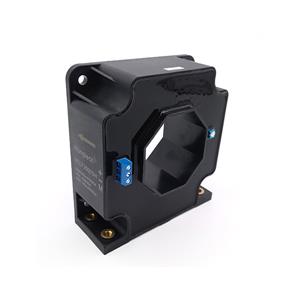
Battery cabinets usually work with high-voltage DC systems and large current paths. The current sensor may be installed around a copper busbar, high-current cable, DC output line, battery string connection, or PCS connection point. Because the sensor is close to high-current conductors, isolation voltage, aperture size, conductor position, and signal wiring should be checked carefully.
Unlike simple current monitoring applications, battery cabinets often require bidirectional current measurement. The system needs to know whether the battery is charging or discharging. If the current direction is reversed, or if the sensor output polarity does not match the BMS or PCS logic, the control system may misjudge the operating state.
Long-term stability is also important. Battery cabinets may operate continuously for years. If the current sensor has high offset drift or poor temperature stability, measurement error may accumulate over time. For this reason, buyers should not choose a battery cabinet current sensor only by price or rated current. The correct model should match the real current range, signal interface, isolation level, and cabinet installation structure.

Typical Current Sensor Positions In Battery Cabinets
Battery charge and discharge main current path.
Battery cabinet DC output busbar.
Battery string connection point.
PCS converter current monitoring point.
DC bus current monitoring point.
Protection circuit or fault diagnosis circuit.
Energy management and current data acquisition system.
2. How To Confirm The Current Range For Battery Cabinet Applications
Current range is the first parameter to confirm. Buyers should provide the normal charge current, normal discharge current, maximum continuous current, peak current, overload current, and fault current if available. A battery cabinet may normally operate at 200A, 300A, 500A, 1000A, or higher, but short-time peak current may be much higher than the rated value.
If the selected current sensor range is too small, it may saturate during peak current or fault conditions. If the range is too large, the sensor may lose measurement resolution during normal operating current. The best current sensor range should provide enough safety margin while still maintaining useful accuracy in the normal charge and discharge range.
For battery cabinets, bidirectional DC current is usually required. The sensor must detect both charging current and discharging current. Buyers should confirm whether the current sensor output uses a zero-current midpoint, positive and negative output, or other signal format. This is especially important when matching the BMS or PCS input.
Peak current duration should also be provided. A sensor that can tolerate a short pulse may not be suitable for long overload operation. If the battery cabinet may experience overload during startup, load switching, emergency discharge, or fault conditions, the buyer should provide peak current value and duration before requesting a quote.
| Current Parameter | Why It Matters | What Buyers Should Provide |
|---|---|---|
| Rated Current | Determines the basic sensor range | 200A, 300A, 500A, 1000A, or project-specific value |
| Peak Current | Prevents saturation during overload or transient operation | Example: 800A peak for 1 second |
| Charge Current | Used for battery charging control and monitoring | Normal and maximum charging current |
| Discharge Current | Used for load supply and discharge protection | Normal and maximum discharge current |
| Bidirectional Measurement | Battery cabinets need charge and discharge direction detection | Confirm bidirectional output and current direction mark |
| Fault Current | Important for abnormal conditions and protection design | Short-time fault current and protection response requirement |

Common Range Selection Mistakes
Choosing only by rated current and ignoring peak current.
Using a unidirectional current sensor for a bidirectional battery system.
Selecting a range that is too large and losing measurement resolution.
Ignoring fault current and overload current during selection.
Not confirming whether the current is continuous or short-time peak.
Not checking whether the sensor output direction matches the BMS or PCS logic.
3. Output Signal Selection: Match The BMS, PCS Or Controller
The output signal of the current sensor must match the battery cabinet control system. Common output signals include 0-5V, 0-10V, ±4V, ±5V, 4-20mA, CAN, RS485, or customized output. If the output signal does not match the BMS, PCS, controller, ADC, or monitoring system, the buyer may need extra signal conversion, which increases cost and project risk.
For bidirectional DC current measurement, the zero-current output point should be clearly defined. Some sensors may output a midpoint voltage at zero current, then increase or decrease depending on current direction. Other sensors may use positive and negative output signals. Buyers should confirm this with the control system before ordering samples.
Supply voltage should also be confirmed. Some current sensors require +5V, +12V, +15V, +24V, or ±15V. If the battery cabinet control board only provides one power rail, the current sensor must match it. Wrong supply voltage may cause unstable output, incorrect readings, or sensor damage.
For long-distance signal transmission inside large battery cabinets or energy storage containers, current output or digital communication may be considered depending on the system design. For compact cabinet-level installation, analog voltage output may be enough if the wiring distance is short and the electrical noise is controlled.
| Output Type | Typical Use | Selection Notes |
|---|---|---|
| 0-5V | Common analog input for BMS or controller | Confirm zero-current point and ADC range |
| 0-10V | Industrial controller or monitoring input | Check controller input range and scaling |
| ±4V / ±5V | Bidirectional current measurement | Suitable when controller supports bipolar signal |
| 4-20mA | Industrial long-distance transmission | Useful for stronger noise resistance and longer wiring |
| CAN / RS485 | Digital monitoring or system communication | Confirm protocol, address, baud rate, and data format |
| Custom Output | OEM battery cabinet or replacement projects | Provide controller input requirement before quotation |

4. Isolation, Installation And Quotation Checklist
Isolation voltage is a critical safety parameter in battery cabinets. The current sensor should safely separate the high-current battery side from the low-voltage signal side. Buyers should provide system voltage, working voltage, isolation voltage requirement, and any certification or insulation requirements. For high-voltage battery systems, isolation should never be reduced only to save cost.
Installation structure should be confirmed before requesting a quote. Battery cabinets often use copper busbars or thick cables. Buyers should provide busbar width, busbar thickness, cable diameter, aperture size, mounting holes, installation direction, and available cabinet space. If these details are missing, the selected current sensor may not fit the real cabinet structure.
Thermal and electrical environment should also be considered. Battery cabinets may work in high-temperature environments, enclosed spaces, energy storage containers, or outdoor power stations. The current sensor should have suitable operating temperature, stable drift performance, and reliable output under real cabinet conditions.
Before requesting a quote, buyers should prepare a complete parameter list. This helps the supplier recommend the correct current sensor model quickly and reduces sample testing risk.
| Information To Provide | Example | Why It Helps |
|---|---|---|
| Application | Battery cabinet / BESS / PCS / DC bus | Helps select suitable current sensor technology |
| Current Range | 500A rated, 800A peak | Prevents saturation and wrong range selection |
| Current Direction | Bidirectional charge/discharge current | Ensures correct BMS or PCS current direction reading |
| Output Signal | 0-5V / ±5V / 4-20mA / CAN / RS485 | Ensures compatibility with BMS, PCS, ADC, or controller |
| Supply Voltage | +5V / +15V / +24V / ±15V | Ensures sensor can work with available power rail |
| Isolation Requirement | 4kV / 6kV / project-specific | Supports high-voltage safety design |
| Conductor Size | Busbar 40 × 6 mm / cable diameter 35 mm | Confirms aperture size and installation fit |
| Quantity | 20 samples, 3000 pcs/year forecast | Improves quotation accuracy and production planning |

Final Selection Checklist
Confirm battery cabinet application and measurement position.
Confirm rated current, peak current, overload current, and fault current.
Confirm bidirectional current measurement requirement.
Match output signal with BMS, PCS, ADC, PLC, or controller input.
Confirm supply voltage and wiring definition.
Check isolation voltage, working voltage, creepage, and clearance.
Confirm aperture size, busbar size, cable diameter, and mounting space.
Check accuracy, offset drift, temperature drift, and long-term stability.
Test the sensor under real cabinet current, temperature, and wiring conditions.
Conclusion
Choosing a current sensor for a battery cabinet requires careful review of current range, bidirectional measurement, output signal, isolation voltage, aperture size, busbar or cable structure, accuracy, drift, response time, operating temperature, and BMS or PCS compatibility.
For battery energy storage cabinets, the right current sensor helps improve charge and discharge current monitoring, BMS calculation, PCS control, protection reliability, and long-term system stability. A complete parameter list allows suppliers to recommend the correct current sensor model faster and provide a more accurate quotation.
FAQ
1. What type of current sensor is used in a battery cabinet?
Battery cabinets commonly use Hall effect current sensors, closed loop current sensors, or customized isolated current sensors depending on current range, accuracy, output signal, and installation structure.
2. Does a battery cabinet need bidirectional current measurement?
In most BESS battery cabinets, yes. The sensor should detect both charging current and discharging current so the BMS or PCS can correctly judge battery operating status.
3. What output signal should I choose?
The output signal should match the BMS, PCS, controller, ADC, PLC, or monitoring system. Common options include 0-5V, 0-10V, ±5V, 4-20mA, CAN, RS485, or customized output.
4. Why is isolation important in battery cabinet current sensors?
Isolation protects the low-voltage control circuit from the high-voltage battery side. It is essential for battery cabinet safety, controller protection, and reliable signal transmission.
5. What should I provide before requesting a quote?
You should provide application, rated current, peak current, charge/discharge direction, output signal, supply voltage, isolation requirement, busbar or cable size, aperture size, operating temperature, sample quantity, and annual demand.
Request A Current Sensor Quote For Battery Cabinet Applications
If you need current sensors for battery cabinets, BESS, PCS converters, battery racks, DC bus monitoring, or charge and discharge current measurement, send us your current range, peak current, output signal, isolation requirement, busbar size, aperture size, BMS or PCS input requirement, and estimated quantity. Our team can help you match a suitable model and provide a practical quotation.
Contact Us Get Quote