Current Sensor Failure Causes And How To Prevent Them
Current Sensor Failure Causes And How To Prevent Them
Current sensors are widely used in motor drives, EV chargers, solar inverters, battery energy storage systems, UPS systems, welding machines, railway power systems, and industrial power supplies. When a current sensor fails or produces unstable readings, the entire system may face control errors, false alarms, overcurrent protection failure, inaccurate monitoring, or unexpected shutdown.
This guide explains the common causes of current sensor failure, how to identify potential risks before mass production, and how engineers and buyers can prevent sensor failures through proper selection, installation, wiring, thermal design, protection design, and supplier quality control.
Quick Answer
Current sensor failure is commonly caused by overload current, incorrect sensor range, insufficient isolation, wiring mistakes, wrong power supply, reversed current direction, excessive temperature, strong electromagnetic interference, mechanical stress, moisture, vibration, poor grounding, and poor installation layout. To prevent failure, buyers should choose the correct current range, check peak current and overload conditions, confirm output signal and supply voltage, provide enough isolation margin, improve thermal design, avoid EMI sources, secure the sensor mechanically, and test the sensor under real operating conditions before mass production.
1. Understand The Most Common Current Sensor Failure Causes
Many current sensor failures happen because the sensor is not matched with the real operating conditions. A sensor may look suitable according to rated current, but real systems often involve peak current, short-time overload current, high temperature, switching noise, vibration, and unexpected fault conditions. If these factors are not considered during selection, the sensor may fail early or produce unstable output.
Overload current is one of the most common risks. In motor drives, startup current and braking conditions can be much higher than rated current. In welding machines, pulse current can create strong short-time stress. In EV chargers and battery energy storage systems, fault current or high discharge current may exceed the sensor range. If the sensor cannot tolerate these conditions, output saturation, overheating, or permanent damage may occur.
Wiring mistakes are another frequent cause of failure. Wrong supply voltage, reversed polarity, incorrect output connection, poor grounding, or wrong terminal connection can damage the internal circuit or produce incorrect readings. This is especially common when replacing an old model with a new model without carefully checking the pin definition and datasheet.
Environmental stress also affects current sensor reliability. High temperature, humidity, dust, vibration, and corrosive environments can reduce sensor life. In high-power cabinets, current sensors may be installed near IGBT modules, SiC MOSFETs, busbars, transformers, DC-link capacitors, and heat sinks. Without proper thermal and mechanical design, long-term stability may suffer.
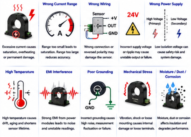
Common Failure Causes
Current range too small for real peak current or overload current.
Sensor saturation caused by high current or magnetic overload.
Wrong supply voltage or reversed power polarity.
Output signal mismatch with controller, ADC, PLC, BMS, or PCS.
Insufficient isolation voltage in high-voltage systems.
High temperature, poor ventilation, or installation near heat sources.
Strong electromagnetic interference from power modules, busbars, or switching circuits.
Mechanical vibration, loose mounting, or terminal stress.
Humidity, dust, corrosion, or poor protection level.
2. Prevent Failure Through Correct Sensor Selection
Failure prevention starts before installation. Buyers should not select a current sensor only by rated current and price. The sensor must match the actual application, measured current type, current range, peak current, response requirement, isolation requirement, output signal, supply voltage, aperture size, and operating environment.
Current range should include enough margin for peak current, startup current, pulse current, overload current, and fault conditions. If the sensor range is too small, the magnetic core or internal circuit may saturate. If the range is too large, normal current measurement resolution may be poor. The right range should balance safety margin and measurement accuracy.
Isolation voltage should be checked carefully in high-voltage applications. EV chargers, battery energy storage systems, solar inverters, UPS systems, and railway power systems may require strong galvanic isolation between the high-current primary side and the low-voltage signal side. Insufficient isolation can cause safety risks and may affect final equipment certification.
The sensor output signal must match the control system. A voltage output sensor cannot always replace a current output sensor. A ± output signal may not match a single-ended ADC. A digital output may require a specific protocol or sampling method. Before ordering, buyers should confirm whether the system needs 0-5V, 0-10V, 4-20mA, ±4V, ±5V, CAN, RS485, or customized output.
For high-reliability projects, buyers should ask for datasheets, wiring diagrams, insulation test data, temperature performance, reliability test reports, EMC information, and quality control documents. This helps reduce the risk of early failure after sample approval or mass production.
| Risk Factor | Possible Failure Result | Prevention Method |
|---|---|---|
| Wrong Current Range | Saturation, inaccurate output, overheating | Confirm rated current, peak current, overload current, and fault current |
| Insufficient Isolation | Safety risk, control circuit damage, certification failure | Check isolation voltage, working voltage, creepage, and clearance |
| Wrong Supply Voltage | Sensor circuit damage or unstable output | Confirm power supply voltage and polarity before wiring |
| Output Signal Mismatch | Wrong reading, signal saturation, controller input error | Match output signal with controller, ADC, PLC, BMS, or PCS |
| High Temperature | Drift, aging, unstable output, reduced lifetime | Improve ventilation and keep sensor away from heat sources |
| Strong EMI | Signal noise, false alarms, measurement fluctuation | Use shielding, proper grounding, and keep distance from switching circuits |
| Mechanical Stress | Loose terminals, cracked housing, unstable contact | Secure mounting and avoid cable pulling or vibration stress |
| Moisture And Dust | Insulation degradation, corrosion, leakage path | Select suitable protection level and avoid humid or polluted installation areas |
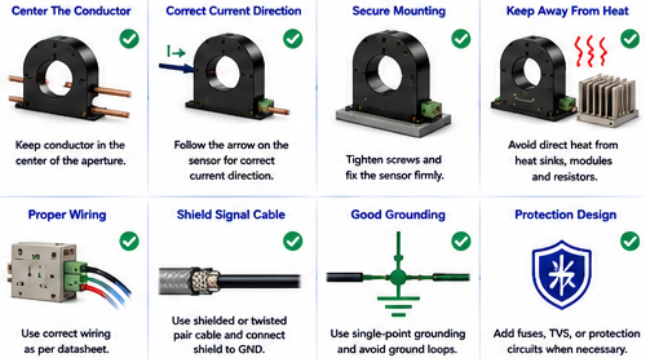
Why Real Operating Conditions Matter
A current sensor may pass a simple room-temperature test but fail in real equipment. Power conversion systems often involve high current, switching noise, temperature rise, vibration, and long operating hours. Before mass production, the sensor should be tested under real load, peak current, high temperature, startup conditions, shutdown conditions, and fault protection scenarios.
3. Prevent Failures During Installation And Long-Term Operation
Correct installation is essential for current sensor reliability. For through-hole sensors, the conductor should usually be centered in the aperture. Off-center installation may increase measurement error and magnetic stress. For split core sensors, the magnetic core should close properly and the locking structure should be secure. For busbar-mounted sensors, the conductor size and installation position must match the sensor design.
Wiring should follow the datasheet. Engineers should check pin definitions, supply voltage, output type, grounding method, signal cable shielding, and wiring direction. Signal cables should be kept away from high-current power cables, motor cables, contactors, and switching devices. In high-noise systems, shielded or twisted-pair cables may be needed.
Thermal design should be reviewed early. Avoid placing the sensor too close to heat sinks, power modules, transformers, braking resistors, or other hot components. High temperature can accelerate aging and increase output drift. In enclosed cabinets, airflow and cooling should be checked under full-load operation.
Mechanical protection also matters. Current sensors installed in welding machines, railway systems, motor drives, and industrial cabinets may face vibration and shock. Loose screws, unstable mounting, cable pulling, and terminal stress can lead to intermittent failure. Secure mounting and strain relief can improve long-term reliability.
Preventive maintenance can reduce field failures. Operators should check abnormal readings, overheating, loose wiring, moisture, dust, corrosion, and unexpected noise. For critical equipment, periodic calibration or comparison with reference measurement can help detect sensor drift or early failure before it causes system downtime.
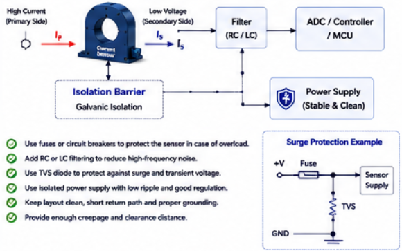
Application Failure Prevention Reference
| Application | Typical Failure Risk | Prevention Focus |
|---|---|---|
| Motor Drives / VFDs | Startup current, switching noise, heat, vibration | Check peak current, bandwidth, EMC layout, and secure mounting |
| EV Charging Stations | High voltage, DC current, heat, output mismatch | Confirm isolation, DC accuracy, output signal, and temperature performance |
| Battery Energy Storage Systems | Bidirectional current error, drift, insulation risk | Use stable bidirectional sensor with low drift and proper isolation |
| Solar Inverters | Outdoor temperature changes, inverter switching noise | Select low-drift sensor and improve shielding, grounding, and cooling |
| Welding Machines | High pulse current, heat, vibration, electrical noise | Check overload capability, duty cycle, response time, and mechanical fixing |
| Railway Power Systems | Vibration, high current, harsh environment, EMC stress | Use high-reliability sensor with strong insulation and anti-interference design |
Final Prevention Checklist
Confirm rated current, peak current, overload current, and fault current.
Check whether the sensor supports AC, DC, pulse, leakage, or bidirectional current.
Match output signal and supply voltage with the control system.
Confirm isolation voltage, working voltage, creepage, and clearance.
Keep the conductor centered and follow the current direction mark.
Separate signal cables from high-power cables and switching circuits.
Keep the sensor away from heat sources and improve ventilation.
Secure the sensor mechanically and avoid vibration or terminal stress.
Test the sensor under real load, peak current, temperature, and EMI conditions.
Conclusion
Current sensor failure is often preventable. The main causes include wrong current range, overload current, incorrect wiring, insufficient isolation, output signal mismatch, high temperature, EMI interference, poor grounding, mechanical stress, humidity, and weak installation layout.
For motor drives, EV chargers, battery energy storage systems, solar inverters, UPS systems, welding machines, railway systems, and industrial power electronics, buyers should select the sensor according to real operating conditions and verify it before mass production. A correct sensor model, proper installation, reliable wiring, strong isolation, good thermal design, and complete testing can significantly reduce failure risk and improve long-term system reliability.
FAQ
1. What are the most common causes of current sensor failure?
Common causes include overload current, wrong current range, wrong wiring, insufficient isolation, high temperature, EMI interference, mechanical vibration, moisture, dust, and poor grounding.
2. Can overload current damage a current sensor?
Yes. If the actual current exceeds the sensor capability, the sensor may saturate, overheat, output incorrect signals, or suffer permanent damage depending on the overload level and duration.
3. Why does wiring cause sensor failure?
Wrong supply voltage, reversed polarity, incorrect output connection, or poor grounding can damage the internal electronics or cause unstable measurement output.
4. How can EMI affect current sensors?
Strong EMI from IGBT modules, SiC MOSFETs, contactors, busbars, transformers, motors, or switching power supplies can cause signal noise, false readings, or unstable output.
5. What information should I provide to avoid wrong sensor selection?
You should provide the application, current type, rated current, peak current, overload condition, accuracy target, isolation requirement, output signal, supply voltage, aperture size, conductor size, operating temperature, and installation environment.
Contact Us For Reliable Current Sensor Selection Support
If you are selecting current sensors for EV chargers, battery energy storage systems, solar inverters, motor drives, UPS systems, welding machines, railway systems, or industrial power electronics, send us your current range, peak current, output signal, isolation requirement, installation layout, and operating environment. Our team can help you reduce failure risk and match a suitable current sensor solution.
Contact Us Get Quote