How To Choose The Right Current Sensor For Different Power System Applications
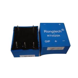
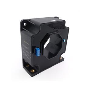
Choosing a current sensor is not just about matching an amperage number on a datasheet. In real power systems, the right choice depends on the application environment, control target, accuracy requirement, isolation need, dynamic response, and long-term stability. Rongtech’s product range itself shows how varied this decision can be, covering open-loop Hall effect current sensors, closed-loop Hall effect current sensors, fluxgate current sensors, voltage sensors, and sensor ICs for use across EV, UPS, motor drive, solar, and industrial power scenarios.
Start With The Actual Power System, Not The Sensor Catalog
The first mistake many teams make is selecting a current sensor by part number popularity instead of by operating condition. A sensor that works well in a UPS may not be the best fit for a motor drive, battery system, solar inverter, or fast-switching converter. Before comparing models, define five basics: current type (DC, AC, or pulsed), nominal current, peak or overload current, bus voltage, and the control purpose. Are you measuring for protection, feedback control, billing-level precision, or simple monitoring? Those answers change the selection logic immediately.
In a drive or inverter system, fast response and strong immunity to electrical noise often matter more than ultra-high static accuracy. In a battery energy storage or EV application, offset drift and long-term stability may become more important because even small errors can accumulate in control or state estimation. In precision power conversion, the sensor must work well not only at rated load but also at low current, transient current, and temperature extremes. That is why sensor selection should begin with the application profile, not just with current range.

Understand The Difference Between Open-Loop, Closed-Loop, And Fluxgate Options
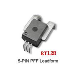
Once the application is clear, the next step is choosing the sensing principle. Open-loop Hall effect current sensors are usually attractive when cost, compactness, and simple integration are priorities. They are often suitable for general industrial use, where the system needs isolated current measurement but does not require the highest possible accuracy. Rongtech’s open-loop line highlights features such as low primary conductor resistance, low power loss, and high inrush current withstand capability, which are especially relevant in power electronics systems with frequent surge events.
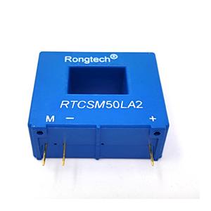
Closed-loop Hall effect current sensors are typically a better fit when the application needs stronger accuracy, better linearity, faster response, and improved temperature stability. Rongtech’s closed-loop models are described as using the Hall effect together with a null-balance method and galvanic isolation, which is exactly why this category is often preferred in higher-performance control systems. If the sensor is part of a feedback loop for an inverter, servo, converter, or protection circuit where measurement quality directly affects system behavior, closed-loop technology is often worth the extra cost.
Fluxgate current sensors move even further toward precision applications. When the system requires extremely low offset, very low drift, and highly stable measurement over time, fluxgate technology may be the better option. This is especially relevant in advanced battery systems, precision test equipment, or high-end energy control platforms where small measurement errors can lead to poor control decisions. The key is not to assume that the most precise technology is always the best choice. For many standard industrial systems, that would only increase cost without improving practical performance.

Focus On The Specifications That Really Affect Field Performance
After choosing the sensor type, the selection should move to practical technical checks. The first is nominal current versus peak current. A sensor that matches only the steady-state current may still fail in an application with startup inrush, short overload pulses, or regenerative conditions. That is why overload capability and inrush tolerance should be checked early, not after the PCB or busbar layout is already fixed.
The second is accuracy under real operating conditions, not just at room temperature. Many teams only compare the basic accuracy number on the front page of a datasheet, but actual performance depends on temperature drift, offset drift, linearity, and repeatability. In high-power systems, temperature rise inside the cabinet can easily change the real measurement error. A good sensor choice should therefore be evaluated across the expected operating temperature range and not only at laboratory conditions.
The third is isolation and safety margin. In power systems, the current sensor is often located close to high-voltage sections, so insulation capability is not a secondary issue. It directly affects safety, control reliability, and system architecture. Galvanic isolation is a major reason Hall-effect and similar sensor technologies are widely used in converters, drives, UPS, and energy systems. If the application involves a high-voltage DC bus, fast switching edges, or strict safety requirements, the isolation design deserves as much attention as the current range.
The fourth is output compatibility. A technically good sensor can still be the wrong choice if its output does not match the controller, ADC, protection board, or signal conditioning stage. Check whether the application needs voltage output, current output, differential signal handling, or direct compatibility with an existing control architecture. Also confirm mechanical window size, mounting direction, conductor routing, and thermal layout. In many projects, these integration factors decide whether the selected part actually works well in production.

Select For System Reliability, Not For Datasheet Appearance
The best current sensor is the one that helps the whole power system perform reliably over time. That means balancing accuracy, response speed, isolation, thermal stability, cost, and integration complexity. For a cost-sensitive industrial product, an open-loop solution may be the smartest choice. For a performance-critical drive or converter, a closed-loop sensor may justify the higher cost. For very high precision control or energy measurement, fluxgate technology may offer the right long-term value. The correct answer depends on what the application truly needs, not on which technology sounds more advanced.
In other words, current sensor selection should always begin with the power system target: what must be measured, how accurately, under what electrical stress, at what temperature, and for what control purpose. Once those questions are answered clearly, the right sensor category usually becomes much easier to identify. That is how engineers reduce selection risk, improve control performance, and avoid paying for features the application does not actually need.